

Putting the ART in ARTificial gravity
This is both an artistic experiment with engineering and a social experiment, given how my usual kind of art (occult symbolism, owls, etc) may feel too complicated for many and it’s often met with indifference. Yeah, aerospace engineering is also complicated (after all, it’s literally “rocket science”), but it feels to me like this kind of subject (hard sci-fi, Star Trek, etc) is more “socially sanctioned” in Fediverse than my usual kind of subject…
Given the latest happening involving my time-lapses (which I’ve been trying to post as a proof of human authorship), this time I’m not posting it. I do have the time-lapse for this art, if anyone is interested in seeing how I drew.
Alt-text:
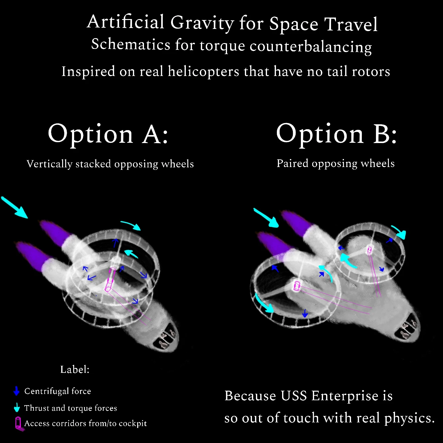
A schematics-like digital art entitled “Artificial gravity for space travel: schematics for torque counterbalancing inspired on real helicopters that have no tail rotors”, divided in two panels.
Both panels feature a isometric view of a faintly translucent spacecraft with a gray hull and front-facing cockpit (whose window shows 3 people inside, one of them upside-down weeee-ing in microgravity behind the other 2) very similar in shape to the NASA’s Space Shuttle (I actually thought of it as I drew), but with a pair of big ionic thrusters (emitting a strong purple glow) at the rear, as well as a pair of large rotating rings attached to the top of the hull, meant as a centrifuge for artificial gravity. The rings, rotating in opposite directions so to cancel out a torque that would otherwise inflict attitude onto the ship (as per Newton’s 3rd Law), are attached through 3 equidistant I-beams to a smaller cylinder (which doubles as a hallway from/to the rest of the ship) which, in turn, is attached to the husk, in different configurations across the panels.
The first panel, “option A: vertically stacked opposing wheels”, is self-descriptive: the rings are on top of each other, rotating in opposite directions in the same axis, much akin to coaxial-rotor helicopters (e.g. Sikorsky S-69).
The second, “option B: paired opposing wheels”, features a configuration akin to transverse-rotor helicopters (e.g. Landgraf H-2), but with a wingspan slightly angled backwards. Each ring is attached to opposite wings.
At the bottom, there’s a label box, describing the meaning of each arrow overlaying both diagrams: cyan arrows represent both the thrust for the ship and rotation for the rings, while blue arrows indicate the gravitational force from the centrifugal motion. A third overlay, painted in magenta, shows the locations for hatches and corridors connecting the inside of each centrifuge to the cockpit and the rest of the ship.
There’s also a jab at Star Trek: “Because USS Enterprise is so out of touch with real physics”, nodding at how Spock and his crew were “simply” able to stand inside the ship as if gravity was something taken for granted outside a planet.
@panda_abyss@lemmy.ca @artshare@lemmy.world
To a certain extent, yes… but I guess it will depend on factors such as the length and the weight of the rings, the weight of the gravitating things sitting on the inner part of the rings (this would be, by far, the biggest contribution to imbalance, no matter the configuration of the rings, as different things, including people, with different weights would be standing on different places across each centrifuge) and the dimensions of the spacecraft, wherein the center of mass tends to be, even with both rings. In option A, the rings are supposed to be as closest as possible to each other, with enough gap for them to rotate without friction.
The main imbalance I can see is during ship’s rotation, especially roll and pitch, given how both configurations only account for yaw balance. So the ship must be as stationary as possible in relation to itself, only changing its attitude when really needed, and doing so in the slowest pace possible, no hurry needed. That’s also why I placed ionic thrusters instead of traditional rocket engines, as ionic thrusters are known to push things really slowly. This spaceship is meant to accelerate extremely slowly.
After I draw this schematics-art, I thought of further configurations, such as Option B with the rings inside a larger husk (so the ship would become more aerodynamic, while also adding some structural strength and weight to further dampen the torque imbalance). Another alternative, for the Option A, would be four rings instead of two, with a pair on the top (as it currently is) and an additional pair on the bottom, which would make the center of mass to match the center of mass of the ship’s hull.